Introduction
The history of mechanical engineering is, in many ways, the history of the gear—the fundamental component that translates motion into power. While the basic principles of interlocking teeth have remained constant for centuries, the methods we use to calculate their geometry, strength, and efficiency have undergone a radical transformation. Today, we stand at the intersection of classical kinematics and artificial intelligence, where the complexity of gear design is being reshaped by digital tools. We are moving away from an era where “good enough” was calculated by hand, into a future where every micron of a tooth profile is optimized for performance, longevity, and silence. This transition is not merely a change in tools, but a fundamental shift in how we perceive mechanical interaction—from rigid, standardized components to fluid, optimized systems that adapt to the extreme demands of the 21st century.
Gear Calculation: The Era of Hand Calculations
Before the advent of CAD (Computer-Aided Design) and CAE (Computer-Aided Engineering), gear calculation was an arduous, manual process that required not just mathematical proficiency, but a deep, intuitive understanding of geometry. In the early days of the Industrial Revolution, gears were often “cast” or “chipped” with significant margins for error. However, as machinery speeds increased—driven by the steam engine and later the internal combustion engine—the need for precision math became the barrier between innovation and mechanical failure.
The Necessity of Hand Calculation
In the early to mid-20th century, an engineer’s desk was defined by slide rules, log tables, and thick volumes of reference charts. Calculating a single pair of spur gears meant navigating the Lewis formula for tooth strength or determining the involute function 
The Lewis formula, developed in 1892, was the gold standard, but it was inherently conservative. It treated the gear tooth as a cantilever beam, focusing purely on the bending stress at the root. However, hand calculations could rarely account for the dynamic loads—the sudden shocks that occur when gears are running at high speed. A mistake in the third decimal place of a trigonometric calculation could lead to a gear set that whined, vibrated, or, in the worst case, suffered catastrophic tooth shear under load. Engineers had to manually plot the “path of contact” and the “line of action” on large drafting boards to ensure that the teeth wouldn’t interfere at the roots. This process often took days for a single gear pair; for a complex gearbox with multiple stages, it could take weeks of verification and cross-checking by multiple departments.
The Depth of Required Knowledge
Back then, you couldn’t simply “input” parameters into a software. To design a gear, you had to be a master of three core pillars:
- Materials Science and Heat Treatment: Understanding the fatigue limits of specific steels and the nuances of heat treatment was a prerequisite. An engineer had to know how much a gear would “distort” during the quenching process and adjust the hand-drawn dimensions to compensate for that future warping. This required a “tribological” intuition—predicting how the lubricant would behave between the metal surfaces under high pressure.
- Kinematics and Geometry: Visualizing how the line of action moves across the tooth profile was essential. This required a grasp of the “Fundamental Law of Gearing,” which states that the common normal at the point of contact between two teeth must always pass through the pitch point. Hand-drawing these involute curves required specialized tools like “involute templates” or tedious point-by-point plotting.
- Manufacturing Constraints: Designing gears that could actually be cut by the hobs and shapers available on the factory floor was the final hurdle. If a design required a tool that didn’t exist or a pressure angle that the machinery couldn’t accommodate, the engineer had to go back to the drawing board. There was no “automated manufacturing” interface; the design was the direct instruction for the machine operator’s manual setup.
This era produced engineers who had a “feel” for the metal—they could look at a gear and tell if the module was appropriate for the torque. However, this high barrier to entry meant that gear design was a specialized craft, often slow, incredibly expensive, and prone to the inevitable human errors of manual calculation.
Gear Calculation Nowadays: The Digital Revolution
Fast forward to the present, and the landscape is unrecognizable. The transition from manual drafting to sophisticated simulation has democratized high-precision engineering, allowing even generalist mechanical engineers to design complex power transmission systems that would have baffled the experts of the 1950s.
A Multitude of Specialized Applications
Today, engineers have access to a vast array of specialized software like KissSoft, MASTA, Romax, and AGMA-compliant calculators. These tools do more than just math; they provide a holistic view of the system:
- Instant Iteration and Parametric Design: Changing a tooth count or pressure angle updates the entire model in milliseconds. Engineers can run “Sensitivity Studies” to see how changing a single variable, such as the helix angle, affects the total efficiency, weight, and cost of the gearbox simultaneously.
- FEA (Finite Element Analysis): Engineers can visualize stress concentrations within the tooth root in three dimensions. Modern software doesn’t just give a number; it provides a color-coded heat map of where the metal is most likely to fatigue. This allows for “lightweighting”—the process of removing material from low-stress areas to create gears that are both stronger and lighter than their ancestors.
- Standardization and Global Compliance: Software ensures that designs automatically adhere to international standards like ISO 6336, DIN 3990, or AGMA 2001. This global language of engineering means a gear designed in Germany can be manufactured in Japan or Brazil with perfect compatibility, ensuring that tolerances are maintained across global supply chains.
The Critical Importance of Gear Calculation
Why do we spend so much energy on these calculations? Because in the world of high-speed machinery, the gear is the single point of failure that can halt an entire system. If a gear fails, it usually doesn’t just stop; it disintegrates, sending high-velocity metal shards through the rest of the machinery, often leading to total system loss.
Example: The Modern Car Transmission and EVs
Consider the automatic transmission in a modern vehicle. It contains multiple planetary gear sets, clutches, and shafts. The gears must handle varying RPMs, sudden torque spikes from aggressive driving, and thermal expansion from hours of highway travel, all while remaining nearly silent to the passengers.
In the past, gear whine was accepted as a part of driving—a mechanical signature of the machine. Today, consumer expectations have shifted toward total cabin isolation. If the gear calculation for the “shift feel” is off by even a few microns, the car will jerk, the fuel economy will drop, and the transmission fluid will overheat due to microscopic friction. In an Electric Vehicle (EV), the stakes are even higher. Without the masking noise of a combustion engine, every mechanical sound is magnified. EV gearboxes often spin at 20,000 RPM or more—speeds that generate centrifugal forces so high they would have shattered a mid-century gear design within minutes. Every tooth must be “micro-geometry optimized” to prevent even the slightest vibration at these extreme velocities.
Comprehensive Breakdown: Gear Types, Parameters, and Calculations
To reach the level of precision required today, engineers must navigate a complex web of inputs and outputs. Here is an exhaustive deep dive into the specific parameters and consequences of different gear geometries.
1. Spur Gears: The Foundation of Kinematics
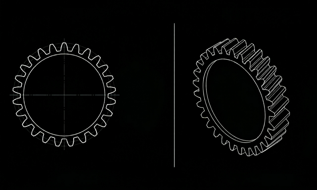
Spur gears are the starting point for all gear education, yet they remain vital in everything from hand tools to aerospace actuators. They are the simplest to calculate but the most prone to noise due to the sudden engagement of the full tooth face.
- Detailed Input Parameters:
- Module (
): The ratio of the pitch diameter to the number of teeth. It defines the size of the tooth. In the US, “Diametral Pitch” is used
, and the conversion between the two is a constant source of error in international projects
.
- Pressure Angle (
): Standardized at
, but
or
are used for specific strength or smoothness requirements. A higher pressure angle increases the load capacity but increases the radial force on the bearings.
- Profile Shift Coefficient (
): Perhaps the most powerful tool in the designer’s arsenal. By shifting the cutter during manufacturing, an engineer can make the teeth thicker at the base (to increase strength) or thinner (to adjust center distances).
- Module (
- The Calculation Process: Modern tools focus on Profile Modification (K-charts). Because teeth deflect under heavy load, they are actually ground “wrong”—a few microns are shaved off the tip and root—so that when they bend under actual operating pressure, they reach the “perfect” involute shape.
- Detailed Output Results:
- Contact Ratio: Must be calculated to ensure that at least one pair of teeth is always engaged. If the ratio falls below 1.0, the gears will “clatter,” leading to instant failure.
- Flash Temperature: A critical output for high-speed gears. It calculates the instantaneous temperature at the contact point, which can be hundreds of degrees higher than the oil temperature, leading to “scuffing” or welding of the teeth.
2. Helical Gears: Managing Three-Dimensional Forces
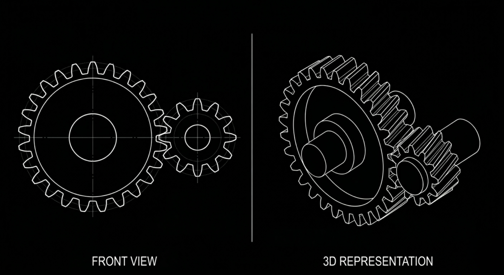
Helical gears are the workhorses of the automotive and industrial worlds because their teeth engage gradually, making them significantly quieter than spur gears.
- Detailed Input Parameters:
- Helix Angle (
): Usually between
and
. While a higher angle increases the “Overlap Ratio” (making the gear quieter), it creates a massive “Axial Thrust” force that tries to push the gear off the shaft.
- Normal vs. Transverse Module: Because the teeth are angled, the tooth looks different from the top than it does from the side. Software must constantly convert between the “Normal” plane (where the tool cuts) and the “Transverse” plane (where the gear rotates).
- Helix Angle (
- The Calculation Process: The math must account for the 3D vector of the load. This requires calculating the “Equivalent Spur Gear” (the virtual gear that would have the same properties) to use standard strength formulas.
- Detailed Output Results:
- Specific Film Thickness (
): Calculated using EHL (Elastohydrodynamic Lubrication) theory. It tells the engineer if the oil film is thick enough to prevent metal-on-metal contact.
- Axial Thrust Force (
): This output dictates the entire housing design. If the
- Specific Film Thickness (
3. Bevel Gears: Intersecting Shaft Geometry
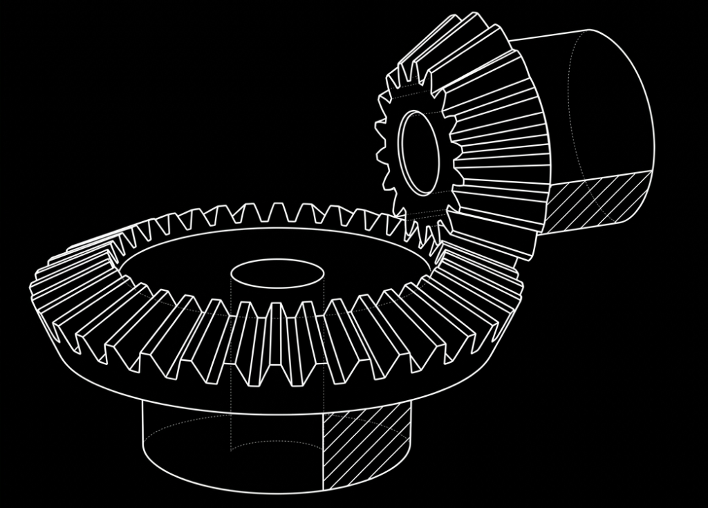
Bevel gears are essentially conical and are used to change the axis of rotation, usually by 90 degrees. Spiral bevel gears, with their curved teeth, represent the pinnacle of classical gear geometry.
- Detailed Input Parameters:
- Outer Cone Distance (
): The distance from the apex to the furthest edge of the tooth.
- Shaft Angle (
): While
is standard, bevel gears can be designed for any angle (e.g.,
or
).
- Outer Cone Distance (
- The Calculation Process: Calculations focus on the Gleason or Klingelnberg System. These are proprietary manufacturing methods that use “Cyclo-Palloid” or “Hypoid” geometries. Hypoid gears (found in rear-wheel-drive cars) are even more complex because the shafts do not intersect, requiring a “Hyperboloid” tooth shape.
- Detailed Output Results:
- Ease-Off Curves: A sophisticated output that shows how the tooth surface has been modified to allow for the gearbox housing to bend under load without concentrating the stress on the edge of the tooth.
- V-H Check: A diagnostic result that tells the assembly team how much “shimming” is required to get the perfect contact pattern.
4. Worm Gears: High Reduction and Thermal Challenges
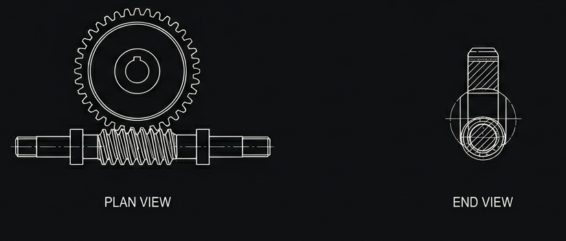
Worm gears provide massive torque multiplication (up to 100:1 in a single stage) but are limited by their low efficiency and high heat generation.
- Detailed Input Parameters:
- Lead Angle (
): If the angle is low (below
), the gear is “self-locking”—it can hold a load in place without a brake.
- Material Pairing: The “Worm” is almost always hardened steel, while the “Wheel” is bronze. Software must calculate the wear rate of the softer bronze over millions of cycles.
- Lead Angle (
- The Calculation Process: The focus is on Thermal Rating. The sliding action is essentially a continuous friction event. The calculation determines the “Heat Dissipation Area” of the housing to see if the gearbox will survive a 24-hour run.
- Detailed Output Results:
- Efficiency (
): Often as low as 60%. This output tells the engineer how much extra motor power is required just to overcome the friction of the gears.
- Lubricant Life: Given the high heat, the tool predicts how often the oil must be changed before it chemically breaks down.
- Efficiency (
5. Planetary (Epicyclic) Gears: High Power Density
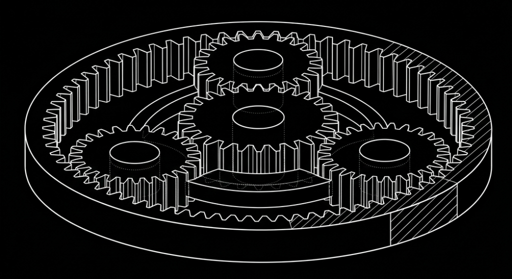
Planetary gears are found in every modern automatic transmission and wind turbine. They are complex because the load is shared between multiple “planet” gears.
- Input Parameters:
- Planet Count: Adding more planets increases torque capacity but makes “mesh phasing” (timing) a nightmare. If the teeth don’t align perfectly, the planets will fight each other, causing vibration.
- The Calculation Process: The math involves Relative Rotational Speeds. While the outer ring might be stationary, the planets are spinning at high speeds while also “orbiting” the sun gear.
- Detailed Output Results:
- Load Distribution Factor (
): In a perfect world, three planets each carry 33.3% of the load. In reality, due to manufacturing errors, one might carry 45%. AI-driven tools optimize the carrier design to be flexible enough to allow the planets to “self-center,” evening out the load.
- Load Distribution Factor (
Industry Standards: The Rulebooks of Gearing
A major part of modern gear calculation is the adherence to standards. Without these, global trade in machinery would be impossible.
- ISO 6336: The international standard for calculating the load capacity of spur and helical gears. It is incredibly rigorous and considers everything from lubricant viscosity to the roughness of the tooth surface. It is the “conservative” standard used in Europe and much of Asia.
- AGMA (American Gear Manufacturers Association): Primarily used in North America. AGMA standards often use different safety factors and are preferred in heavy industrial and oil/gas applications. A “Class 12” AGMA gear is a high-precision component.
- DIN (German Institute for Standardization): Known for being the most precise regarding manufacturing tolerances. The DIN quality grades (e.g., DIN 1 to DIN 12) define the allowable “Runout” and “Pitch Error” in microns.
Modern software allows an engineer to toggle between these standards with a single click, comparing how a gear designed for a European market might perform under American safety regulations—a process that used to require months of manual translation of formulas.
Material Science and Metallurgy in Gear Design
A gear’s geometry is only half the battle; the other half is the Metallurgy. A mathematically perfect gear made of the wrong material is just an expensive paperweight.
- Case Hardening (Carburizing): The most common process for high-performance gears. The gear is “soaked” in a carbon-rich atmosphere at high temperatures, then quenched. This creates a diamond-hard outer “case” to resist wear, while keeping a tough, ductile “core” to absorb shocks. Calculation tools now predict the “Effective Case Depth” (ECD) required for specific loads.
- Nitriding: Used for gears that cannot be distorted by high heat. It is a lower-temperature process that introduces nitrogen into the surface. Tools calculate the “White Layer” thickness, which must be carefully managed to prevent the surface from becoming too brittle and “spalling” off.
- Shot Peening: A post-processing calculation where the gear is bombarded with tiny steel beads to create “compressive residual stress.” This essentially “pre-squeezes” the metal, making it much harder for fatigue cracks to start.
The Difficulty of Modern Gear Design: The “Involute” Mystery
Despite the tools, gear design remains one of the most challenging fields in mechanical engineering. The difficulty stems from the Involute Profile.
The curve of a gear tooth is not a simple arc; it is a mathematical curve that ensures a constant speed ratio even as the teeth slide against each other. If the teeth are slightly off-profile—due to wear, poor calculation, or manufacturing tolerances—the velocity of the driven gear will fluctuate, even if the input speed is constant. This causes Transmission Error (TE).
TE is the “Holy Grail” of gear design. If you can minimize TE, you can make a gearbox that is virtually silent and lasts for decades. However, TE changes depending on how much torque is applied. A gear that is perfect at low torque might vibrate violently at high torque as the teeth bend. This “Dynamic Behavior” is what separates amateur gear designers from professionals. Modern software uses Dynamic Simulation to predict how the entire housing, shafts, and bearings will flex together, ensuring the gears stay aligned under the most extreme conditions.
How Easy is Gear Calculation Nowadays with AI?
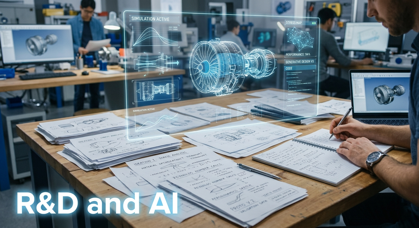
AI has effectively removed the “grind” from the engineering process, acting as a force multiplier for human designers. We are moving from “Design by Calculation” to “Design by Optimization.”
Generative Design and Evolutionary Algorithms
Instead of an engineer drawing a gear, they define the “environment”: torque, speed, space constraints, and life expectancy. AI uses Generative Design to “grow” the gear shape through thousands of iterations. This often results in organic-looking structures—gears with spider-web-like spokes or variable-thickness webs that reduce weight by 40% while maintaining the exact same stiffness. This is revolutionary for the aerospace industry, where every kilogram saved translates to thousands of dollars in fuel savings over the life of an aircraft.
Predictive Maintenance and Digital Twins
AI is now being used to create “Digital Twins” of gears in the field. Sensors on a wind turbine or a ship’s engine send real-time data to a cloud-based calculation model. The AI compares the actual vibration signature to the theoretical “perfect” model. If it detects a slight shift in frequency, it can predict exactly when a gear will fail, allowing the company to replace it before it breaks, saving millions in downtime.
AI in NVH (Noise, Vibration, Harshness)
Modern AI tools can analyze the microscopic tooth surface topography. They can suggest “Lead Crown” or “Involute Slope” modifications—microscopic changes to the tooth shape (sometimes as small as 2 microns)—to cancel out specific sound frequencies. This is why modern luxury cars are so quiet; the gears are “tuned” like musical instruments to be silent at highway speeds.
The Specialized Case: Cycloid Gears
While involute gears dominate 90% of the market, the Cycloid Gear is a masterpiece of calculation. Unlike the involute, the cycloid tooth is formed by a point on a circle rolling along another circle.
Why use Cycloid?
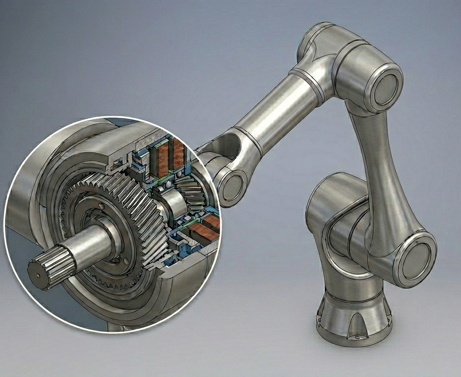
Cycloid gears are found where Zero Backlash is required. In a robotic arm used for surgery, a backlash (play) of even 0.1mm could be the difference between a successful procedure and a tragedy. Cycloid drives (or Harmonic Drives) are used because they are “Backdrive-Resistant” and incredibly compact. They allow a robot to hold a heavy weight in a precise position for hours without the arm “sagging” due to gaps in the teeth.
The Calculation Challenge
Calculating a cycloid gear is significantly harder than an involute gear. It involves complex parametric equations and requires extreme manufacturing precision (often sub-micron). If the “pins” in a cycloid drive are off by even 5 microns, the internal friction will cause the drive to seize or wear out in hours. However, modern AI-enhanced tools have made designing these “exotic” gears as easy as designing a standard spur gear, allowing for a surge in high-precision robotics across the medical and manufacturing sectors.
Manufacturing Technology: From Hobbing to 5-Axis Milling
Calculation is only as good as the ability to manufacture the result. The evolution of tools has mirrored the evolution of the machines.
- Hobbing and Shaping: The traditional methods. The calculation tools generate “G-code” or “Tool Paths” that tell a specialized machine how to “synchronize” the rotation of the blank with the cutting tool.
- Power Skiving: A high-speed modern process that is 5 to 10 times faster than shaping. It requires incredible synchronization and was only made possible by modern high-speed controllers and the software capable of calculating the complex 3D tool engagement.
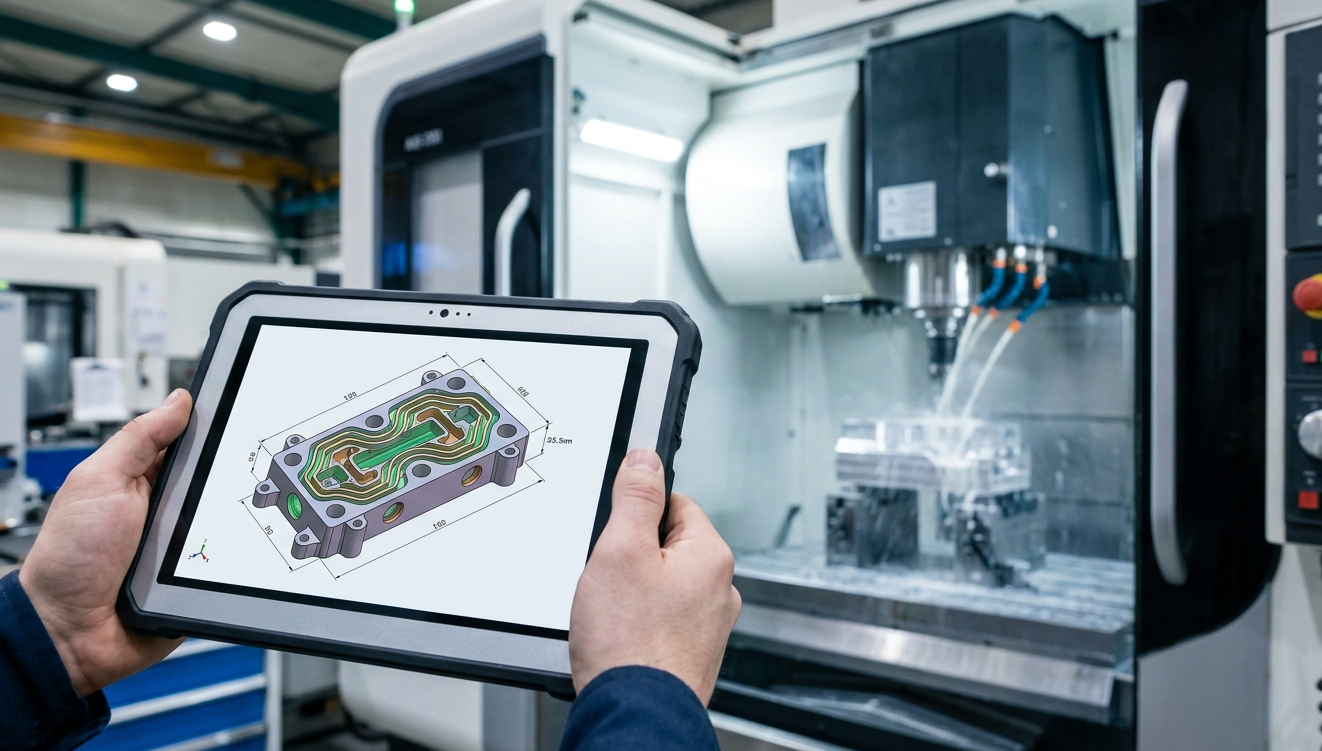
- 5-Axis CNC Milling: Formerly too slow for production, modern 5-axis mills can now cut complex bevel and helical gears using standard tools. The calculation software treats the gear as a “Free-Form Surface,” allowing for totally custom tooth shapes that don’t conform to any standard but offer superior performance.
Expected User Outputs from Modern Tools
When an engineer finishes a calculation today, they don’t just get a “Pass/Fail.” They receive a comprehensive digital package containing:
- Safety Maps (3D): A graph showing safety factors across a range of speeds and torques, highlighting the “danger zones” where the gear might fail.
- Contact Pattern Simulation: A video or high-res image showing exactly where the teeth touch under load. If the contact reaches the edge of the tooth (Edge Loading), the software flags it as a critical failure risk.
- Efficiency and Power Loss Curves: A breakdown of how much power is lost to oil churning, windage (air resistance at high speeds), and tooth friction.
- CAD/CAM Export: A perfect 3D model (STEP, IGES, or DXF) that can be sent directly to a CNC machine or a 3D printer for rapid prototyping.
Conclusion
The advancement of gear calculation tools marks a transition from “artisan engineering” to “data-driven precision.” We have reached a point where we can generate designs that are mathematically perfect, quiet, and incredibly durable with just a few clicks. With the integration of AI and real-time simulation, we are no longer just checking if a gear will break; we are optimizing it to the very limits of physics.
However, a word of caution to the modern engineer: while AI and software are powerful, they are tools, not replacements for understanding. Engineers should not forget the old methods—the hand calculations and the fundamental physics. Knowing why a gear fails at the root—understanding the Lewis formula or the Hertzian contact stress—is more important than knowing which button to press. The software can tell you that a gear will fail, but only a deep understanding of the mechanics can tell you how to fix the design. By combining the soul of classical engineering with the speed of modern technology, we can continue to drive the world forward with even greater efficiency and reliability.